Replacing the optics assembly on a Whirlpool refrigerator should follow a confirmed circuit fault. The receiver and emitter belong to an ice-level sensing system, so a no-ice complaint alone is not enough to order either board. The right decision connects the observed bin response to the exact refrigerator design.
What This Symptom or Part Can and Cannot Prove
- Optics behavior is evidence about the sensing circuit.
- A stationary bin-state reading can have more than one electrical cause.
- A new board cannot correct an unresolved fault elsewhere in the circuit.
Distinguish a replacement decision from a general no-ice search. The goal here is to decide whether an optics part is supported by the evidence. The record should make clear what was observed before any cover was removed and who completed any electrical measurement.
Verify Your Model First
Find the Refrigerator model tag before ordering. Record the full model number, including its suffix, because parts with the same name can use different connectors, dimensions, ratings or mounting points across models.
Use the interior refrigerator identification label and owner manual to confirm the control layout. Whirlpool ice-level optics can have different arrangements on side-by-side and French-door refrigerators. Door style alone cannot confirm the board positions or compatible parts.
The full appliance model number must come from the identification label on the appliance, rather than the front badge or an old order receipt. A clear photo makes a useful record when the refrigerator is difficult to reach. The serial number can help identify a production change, but it does not replace the model number.
Safety Before Testing
- Unplug the refrigerator before handling boards or connectors.
- Keep connector testing with power applied for a qualified technician.
- Protect hands from sharp access-panel edges.
- Keep water away from electrical components.
- Photograph accessible wiring before it is disturbed.
- Reinstall protective covers before normal use.
Causes to Check Before Buying a Part
| Cause | Evidence | Safe check | What the result means |
| Optics circuit fault | Bin report stays incorrect | Run the matching enclosed-panel check | Continue diagnosis before ordering |
| Supply or interface fault | Optics fault has not been electrically isolated | Have the technician check the correct circuit | A board swap may not address the cause |
| Model mismatch | Board arrangement differs from the diagram | Check full model and suffix | Confirm the correct model-specific method |
Once the test identifies the failed part, confirm the exact replacement with the full model number. Use that category only when the diagnosis identifies a failed optics control board; a different finding needs its own matching part.
Safe Testing and Repair Order
Rule Out Access, Power, Airflow, Water-Flow or Obstruction Causes as Applicable
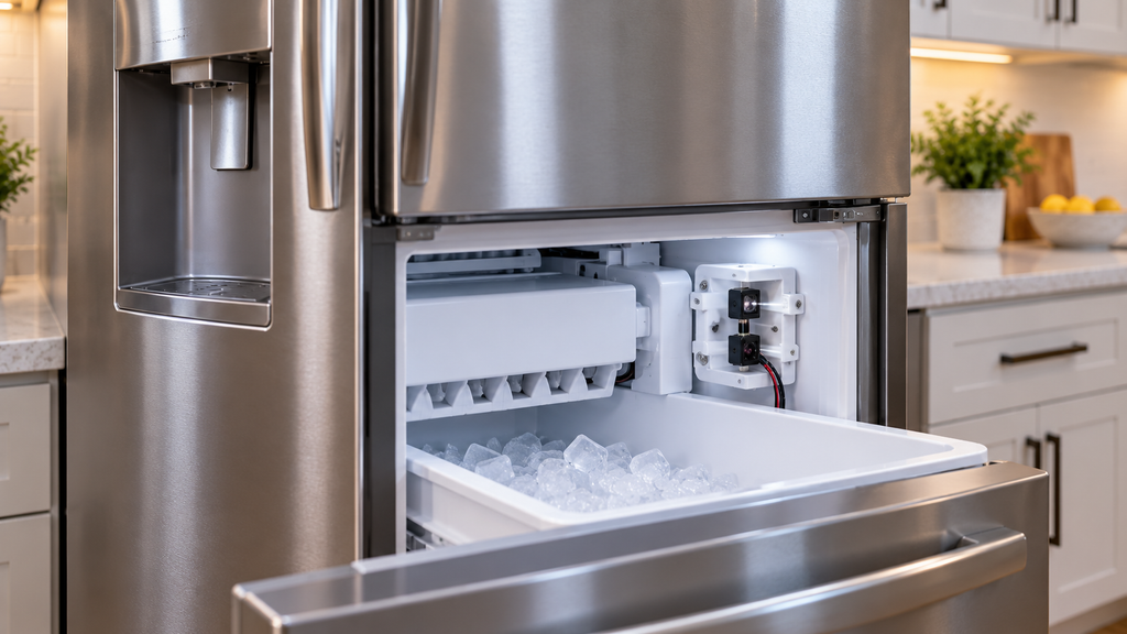
Start with the documented control layout. Treat the receiver and emitter as separate diagram positions when recording the system. The bin must be described in its actual position, because a result written without that context is hard to interpret later. Do not remove a cover merely to look for a familiar part number.
Check the Covered Optics System in Diagnostics
- Close both doors.
- Hold the two left controls.
- Wait for the countdown, tones and 01.
- Use the fifth control to scroll; the fourth goes back.
- Select test 15 and wait for its result.
- 01 indicates a full or absent bin.
- 02 indicates a bin that is not full.
- Open the left door and remove the bin.
- Check for the change from 02 to 01.
- For 01 already displayed, check ON and the flapper without blocking the beam.
- Correct responses support normal optics operation.
- A stuck response requires circuit diagnosis.
- Hold both left controls to exit.
- Disconnect power before accessing the system.
The refrigerator design determines the optics assembly access and mounting points. Side-by-side and French-door arrangements require separate repair methods. A technician should complete the powered supply check and identify which board, if any, needs replacement.
Interpret the Result
The diagnostic display is useful only with the bin condition recorded. A normal response supports leaving the optics alone while another cause is investigated. An abnormal response supports further testing, rather than automatic replacement. Use the conditional link only after the circuit diagnosis confirms an optics board.
Test result confirmed the failure? Find the exact optics control board for this model number. This purchase step applies only after the stated evidence is present.
How to Identify the Correct Replacement for This Model
Confirm the failed board’s position on the model diagram. Check the current service part number against the original number, including any documented supersession. A replacement kit may differ from a single board listing; compare what the listing supplies with what the model requires.
Match the full model to the manufacturer’s parts diagram before selecting a replacement part. A part name identifies the component type, while the diagram and compatible service number establish which version belongs in this appliance. A similar-looking photo can help with orientation, but it cannot confirm fit by itself.
Keep these records together:
- The full model number and suffix.
- The diagram position and current replacement part number.
- The observation or test result that led to the repair.
- A photo of the original part and its connections, where safely accessible.
Do not place an order while an unresolved model difference changes the repair method. Ask the supplier to check a superseded number against the actual appliance. The correct order should describe both the compatible part and the evidence for replacing it.
When to Stop and Call a Professional
- The repair method does not match the appliance layout.
- A measurement requires exposed wiring with power on.
- Board connectors or the door harness show damage.
- The diagnosis remains “optics or control” without identifying either.
Ask for the recorded circuit result with the service diagnosis. The important detail is why a particular board was selected, not merely that a new optics kit was suggested. That explanation helps the supplier verify the correct replacement and avoids treating a normal diagnostic response as a failure.
FAQ
What should be checked before an optics assembly is replaced?
Check the full model and run only the matching intact-panel diagnostic. Record the bin position alongside the result so the reading has a clear meaning.
How can a failed optics assembly be distinguished from another fault?
The interface check narrows the sensing complaint. Electrical circuit diagnosis separates the optics boards from a supply or control problem. The interface reading alone may not identify the failed part.
What safe result confirms the part should be ordered?
A technician’s completed, model-specific diagnosis should identify the failed board. A wrong bin reading by itself supports more testing rather than a confirmed order.
Why is the full model suffix required?
The suffix can change the board arrangement and compatible part. Read it directly from the identification label instead of choosing a listing from a similar refrigerator photo.
When should a professional take over?
Have a professional take over before exposed powered testing. Also ask for help when the documented door arrangement differs from the actual refrigerator.
After the diagnosis is settled, find the correct optics control board for your model. Keep the model record with the order so the repair starts with a verified match.
In Summary
An optics replacement is easier to justify when the circuit result identifies the board and the diagram confirms its fit. Keep those two decisions separate. The refrigerator can then receive the supported repair without an unnecessary kit purchase.
The last step is the part itself: match a refrigerator control board parts to your model number rather than to a photo or a part name.